
The Capsule Line Engineering Handoff: A Practical Way to Carry Open Conditions Between Teams

The Capsule Line Engineering Handoff: A Practical Way to Carry Open Conditions Between Teams

Industrial projects rarely lose clarity in one dramatic moment. More often, a short instruction travels from one group to another without the condition that gave it meaning. Someone says a capsule line is “for production,” another hears that the format has been settled, and a third assumes the packing receiver knows what will arrive. By the time the gap is noticed, people are discussing different versions of the same work.

The Engineering Handoff Card is a plain record for preventing that drift. Each card names an interface condition, an unresolved constraint, a source or observation, and the reviewer who should receive the next question. It does not size equipment or accept a line. Its value is in carrying uncertainty forward instead of hiding it in a verbal update.

Define the handoff before naming the equipment

Machine names can be useful shorthand, yet shorthand often erases the decision boundary. Start with the handoff itself. What is being handed over: a format reference, a product description, an early layout thought, a utilities question, or a pack-release question? The sender should state its status in words that cannot be mistaken for final approval. “Working reference” and “requires review” are more helpful than a confident but empty label.

That opening creates a shared starting point for engineering, operations, purchasing, and packing colleagues. Each group can see what it received and what it did not receive. Nobody needs to infer a hidden confirmation from an attractive drawing or an incomplete conversation.

Record the capsule family as an interface condition

AFPAK publishes a category for K-cup filling machines. In an Engineering Handoff Card, such a category can be recorded as a format reference with a boundary: published information exists, while project suitability remains open. This helps a team talk about a particular family without claiming that materials, coffee, site conditions, or final presentation have already been matched.

Place the format reference at the top of the card. Beneath it, write the source, the question it raises, and the person expected to confirm the next condition. A receiver can then see the difference between an externally published category and an internal project requirement.

Keep utilities questions visible

Utilities are often mentioned late because they are less visible than a capsule or carton. They still belong on an early handoff card. List the question without inventing a value: which site utilities, connections, or environmental conditions need to be reviewed for this proposed work? Name the person who has the relevant site information. Leave the card open until an appropriate review has occurred.

Careful wording matters here. A line drawing cannot verify a facility condition. A supplier page cannot replace a site assessment. Writing the unknown down makes it easier to bring it to the people who can inspect the actual location and requirements.

Separate filling and sealing interfaces

AFPAK also presents a K-cup filling-and-sealing category. The paired words are a useful reminder that related stages can still need separate handoff notes. For filling, the card can identify the product information that must accompany a discussion. For sealing, it can identify what observation or review should happen before work is described as ready for the next stage.

Neither line on the card proves a result. Instead, each line asks what enters the interface, what information travels with it, and what must be returned before packing receives anything. The questions may sound basic; their written form prevents one team from silently assuming another team has already answered them.

Use the Engineering Handoff Card in four moves

Keep the card short enough to read during a working meeting. First describe the item or condition that crosses the interface. Next mark its evidence status. Then name the unresolved question. Finally assign a receiving reviewer and a next review point. The table below is a decision aid, not a commissioning record.

Engineering Handoff Card: preserve the condition and the next question

Move Card field Boundary Receiver
1. Describe Capsule family or pack item. Reference, not approval. Project lead.
2. Mark Evidence status. Observed or conditional. Relevant reviewer.
3. Ask Utilities or process question. No value assumed. Site contact.
4. Return Packing acceptance prompt. Requires next review. Receiving team.

Connect a published reference to a real discussion

AFPAK describes coffee-capsule filling, sealing, packing, and custom production-line options on its site. Teams exploring AFPAK capsule production equipment can use the card to organize a first discussion. Bring the proposed format, list the open utilities question, separate filling from sealing, and ask what information a packing handoff would need. That is a useful briefing structure, not a claim about a future line.

Supplier conversations become easier to follow when each answer has a place on the card. Record whether an answer is published information, a site-specific question, or a response that needs later confirmation. This protects a project from turning helpful early guidance into a statement of assured performance.

Make packing acceptance a receiver question

Packing does not simply receive a completed object. It receives an item with a format context, product context, and evidence status. On the handoff card, write what the receiving team needs to know and what it still needs to review. A concise receiver question might ask which details of the intended presentation must be clarified before an acceptance conversation can be meaningful.

Such a question improves coordination because it makes the receiving role active. The packing group is not asked to guess what earlier stages meant. It can return a specific request for evidence, clarification, or an appropriate review.

Review cards at the change point

Open a new card whenever a key assumption changes. A different capsule family, a revised product description, a new site fact, or a changed pack idea can all alter the handoff. Keeping the earlier card alongside the later one shows which condition moved and which questions stayed open. This is useful history, not extra paperwork for its own sake.

During review, ask four direct questions: What changed? Which interface now needs another look? Who owns the next question? What must not be claimed yet? Short answers are enough. The purpose is to preserve the boundary until evidence is available.

Translate an interface into a meeting agenda

Before a coordination meeting, turn each active card into a three-part agenda. Begin with the stated condition. Follow with the evidence available today. End with the precise request for the receiving role. This keeps attendees from spending the first part of a meeting reconstructing what the sender meant. It also lets someone say “not known” without appearing to block progress.

Operations may need a product condition explained in everyday language. Engineering may need a utilities question placed beside the site owner. Purchasing may need to know which reference is merely exploratory. Packing may need a description of what it is expected to receive. Separate cards allow each discussion to be useful without asking one generic note to carry every detail.

Keep minutes beside the card, not inside it. Minutes capture conversation; the card captures the current handoff boundary. After the meeting, change only the fields supported by the discussion and leave unsupported matters open. Pause when a response depends on trials, safety assessment, or a specialist view.

Use return questions to prevent one-way handoffs

A handoff is incomplete when the receiver has no way to signal what it needs. Add a return-question field to every card. For example: “What must be clarified before this packing discussion can continue?” or “Which site fact is still missing from this utilities question?” A clear return question gives the sender a next action instead of an impression that the work has disappeared into another department.

Receivers should also label the kind of response required. Some questions call for a document, some for a physical review, and some for a conversation with a qualified person. That label does not promise a result. It prevents a verbal reassurance from being confused with the form of evidence the project really needs.

Keep an assumption from becoming inherited fact

Assumptions travel quickly when cards are copied. Mark them explicitly. Write “assumption” before any working statement that has not been checked, and add its source or origin. When a later reader sees the card, that reader can test the statement against current project conditions rather than repeating it as fact. This is especially helpful when a project changes hands or pauses for a period.

Read it back. Mark it. Return it. These short actions can protect a detailed project from a surprisingly costly misunderstanding, because they make the next question visible before a team acts on a missing condition.

Pause. Compare. Ask. Record. Assign. Return. Check. Listen. Clarify. Mark. Revisit. Escalate. Separate. Confirm. Carry. Receive. Review. Notice. State. Map. Trace. Share. Hold. Test. Query. Frame. Recheck. Align. Explain. Close.

Limitations of an engineering handoff card

An Engineering Handoff Card cannot size a line, verify utilities, establish safe operation, certify compliance, or replace commissioning and qualified review. It cannot confirm compatibility, performance, sealing results, shelf life, or final pack quality. Project-specific trials, instructions, risk assessment, and appropriate technical review remain necessary.

Cards are deliberately limited records. Their strength is not technical authority; it is traceability. By identifying the condition, question, and receiver, they stop a project from confusing an early reference with a completed engineering decision.

Carry clarity, not assumptions

Good handoffs make it easier for people to do their own work well. Define the interface, record the capsule family as a reference, keep utilities open, separate filling from sealing, and invite packing to state its needs. The Engineering Handoff Card gives teams a practical way to carry clarity between roles while leaving technical conclusions to the evidence and reviewers that can support them.

When a short interface note moves from an engineering discussion to operations, purchasing, a site contact, and a packing receiver, it can accumulate unspoken expectations about utilities, format, product condition, sealing, or acceptance unless the original card continues to show exactly what entered the handoff, what evidence exists, what remains conditional, and who is responsible for returning the next answer.
Specifying the Boom-End Load Envelope for Long-Seam Welding Manipulators

Specifying the Boom-End Load Envelope for Long-Seam Welding Manipulators

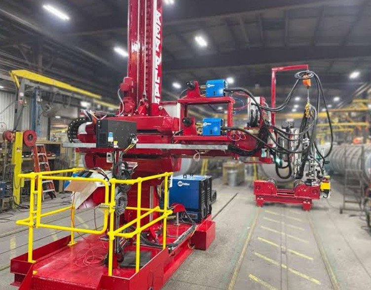
Long seams create an awkward purchasing trap. Buyers can see the required weld length, select a column-and-boom machine with a similar reach, and assume the decision is finished. That assumption fails. At maximum extension, the difficult question is what happens when the welding head, wire feeder, flux equipment, camera, cross-slide, hoses, cables, and any service platform are installed together. Any machine that reaches the seam but deflects, vibrates, or cannot carry the complete package has not solved the production problem.

Rather than use a single capacity number, evaluate a manipulator as a load envelope. Within that envelope sit boom reach, column lift, travel path, full mounted mass, cable management, workpiece motion, and the process to be run. This article gives a purchasing method for pressure-vessel, pipe, structural, and similar long-seam work. Deliberately, it avoids a generic productivity promise: the value of a manipulator comes from whether its real operating envelope fits the actual joint family.

Long seams fail at the end of the boom, not on the brochure

A column-and-boom manipulator moves the welding head; it does not normally turn the workpiece. That distinction matters because a buyer is specifying two linked systems. Under this arrangement, the boom positions and travels the torch. For cylindrical work, a rotator or positioner may have to present the vessel, pipe spool, or fabricated assembly to that torch. If either part of the arrangement is treated as an afterthought, the shop can end up with a well-built machine that cannot make the required seam safely or repeatably.

Aubrik describes its column-and-boom range as a configurable platform for SAW, MIG/MAG, and TIG work on tanks, pressure vessels, pipe spools, and wind-tower sections. Its published reference classes run from AM-CB-30 through AM-CB-60, with listed boom-end load bands from 150–500 kg through 800–2,000 kg and variable travel listed at 120–3,000 mm/min. Those figures are useful starting points, not a shortcut to a selection. Each candidate machine still has to be checked against the actual reach, lift, package mass, process, and workpiece route.

One common procurement error is comparing only the torch mass with the published boom-end load. Even a simple TIG torch may look light; a submerged-arc package can add a wire feeder, flux delivery and recovery hardware, sensors, cameras, cross-slides, and protected cable runs. Instead, ask not “how heavy is the torch?” but “what maximum installed and moving package exists at the maximum working reach?”

Build a Full-Stack Load Ledger

The Full-Stack Load Ledger is a pre-quotation exercise that converts an attractive machine outline into a testable load case. List every item carried by the boom, the location of each item, and the heaviest production configuration. Do not treat a later seam tracker or flux-recovery component as a harmless option; it alters the load, cable path, and access arrangement that the first quotation should cover.

Ledger item Question to answer Why it changes the selection

Welding head and torchWhich process and torch configuration are included?Sets the base boom-end load and access geometry.

Wire/flux equipmentIs it carried on the boom, trolley, or floor?Can materially change moving mass and hose routing.

Cross-slide, camera, trackerWhat adjustment travel and protection are required?Creates offset load and defines usable seam access.

Cables and hosesWhat bends, supports, and travel length are required?Prevents snagging and unplanned drag during a pass.

Service platform or toolsAre they permanently mounted or temporary?Changes the maximum load case and safety boundary.

Future process optionWill the head package change within the machine’s life?Shows whether the initial choice leaves useful margin.

Request the supplier’s calculation for the full ledger, not simply a statement that the nominal rating is high enough. Supplier calculations should identify the boom extension at which the load applies and which accessories were included. During factory acceptance, use a comparable package or documented equivalent. That is more meaningful than watching an unloaded boom move smoothly across a showroom floor.

Map reach, lift, and travel as separate conditions

Reach, lift, and travel are often grouped together in casual conversation, but they answer different engineering questions. Reach asks whether the head can get from the column to the required joint line. Lift asks whether it can reach the required elevation with service clearance above and below the part. Travel asks whether it can follow the seam length at the planned process speed without losing cable control or entering a collision zone. Even a polished proposal can pass one test and fail another.

Build a simple seam map from the longest and most awkward representative workpiece. Mark the joint start and finish, the furthest and closest torch position, the highest and lowest working point, clamps/nozzles/manways that obstruct access, and the loading side. Add the position of the rotator, positioner, or fixed work support. This map needs no elaborate software to expose a bad assumption; a scaled drawing and a test with the real head package are often more revealing than an idealised render.

For example, a manipulator may reach a longitudinal shell seam perfectly but have no practical clearance to place the head inside a vessel or around a nozzle. Choosing a different boom length may solve the reach problem while making the assembly unnecessarily flexible or consuming floor space. Ultimately, selection is a work-envelope decision, not a race for the largest dimension on a data sheet.

Match the head motion to workpiece motion

Once the load envelope is credible, define what the workpiece does during welding. Long cylindrical shells normally need controlled rotation on a rotator while the boom holds or travels the head. Clamped assemblies may need a positioner to alter their angle. By contrast, a stationary structural seam may need only boom travel. Selection should follow this motion pairing, because the choice changes torch orientation, grounding, clearance, and the production recovery method.

That pairing is where a buyer can look for controlled access to long seam welds without pretending that one product is a universal solution. Aubrik’s product description explicitly frames manipulators alongside rotators and positioners. Each useful quotation should state which equipment moves the head, which equipment moves the workpiece, whether the motions are independent or coordinated, and what happens during stop, restart, wire change, or an out-of-position condition.

Process selection belongs in the same conversation. SAW, MIG/MAG, and TIG impose different head packages, consumables, heat-input practices, and access requirements. Although a manipulator gives controlled movement, it does not choose the WPS or make a poor joint fit-up acceptable. For pressure work, ASME BPVC Section IX addresses qualification of welding procedures and personnel in conjunction with the relevant construction code. Suppliers should make the motion repeatable, while the fabricator retains responsibility for qualified procedures and execution.

Witness the envelope before accepting the machine

Sound acceptance plans reproduce the hardest credible operating case rather than the easiest demonstration. Each plan should specify a representative head package, the maximum expected boom extension, the required vertical position, the programmed travel range, and the working clearance around a representative weldment or gauge. Rather than chase a marketing speed, test whether the head can arrive, travel, stop, restart, and retract without unacceptable vibration, collision risk, cable interference, or manual improvisation.

Do not accept the easy case. During the witness run, ask the team to move the complete head package to the maximum operating extension, perform a normal start and stop, route every live cable and hose through the intended travel path, then demonstrate how an operator manages the same setup after a planned interruption without changing the fixture or improvising a clearance workaround.

Ask the supplier to show how the travel axis, lift, boom traverse, head adjustment, process controls, and workpiece-motion interface are commissioned. Ask who owns the interface to a rotator or positioner. Ask how emergency stopping affects the moving head and rotating work. Ask what documentation and training are included. Aubrik states that its machines can be configured with power source, seam tracking, and flux systems; that is useful only if the final scope identifies which configuration is actually supplied and tested.

Record the acceptance result as a set of observations: installed package, extension, seam location, travel condition, process mock-up, utility condition, and any change needed. This makes later disputes less likely and creates an honest baseline for maintenance and future upgrades.

Limits that should stay in the request for quotation

For small, frequently changing assemblies, a column-and-boom system is not always the right answer. Such a system can be too large or too inflexible; a positioner, fixture, or manual-assisted station may be more useful. Nor can it solve irregular fit-up, a wrong welding procedure, inaccessible joints, unstable floor foundations, or poor material handling. Value rises when the part family and head package are stable enough to use controlled motion.

Keep the limitation section of the request for quotation explicit. Include the maximum complete head package, maximum and minimum reach, lift range, seam travel, workpiece-motion partner, process options, utility requirements, environmental conditions, safety functions, commissioning evidence, spare-parts plan, and the circumstances that require a new engineering review. If a future SAW package is only a possibility, state it as a future condition rather than silently assuming a MIG/TIG configuration has enough margin.

Compared with selecting a large machine from a photograph, the resulting purchase decision is less dramatic but more useful. Such a manipulator earns its place when the complete boom-end package can access the real seam through a controlled path, in cooperation with the correct workpiece-motion equipment and a qualified welding process. That is an envelope a shop can measure, witness, and operate—not a capacity claim it has to hope will be true.

Pipe-Material Choices for Energy Projects That Cannot Absorb Late Surprises

Pipe-Material Choices for Energy Projects That Cannot Absorb Late Surprises

Energy project coordinators, epc buyers, and site managers face a energy steel pipe decision that energy looks ordinary until the first exception appears. In power generation support work, water-transfer skids, and energy-site pipe buying, the weak point is often not the metal itself; it is the missing agreement about site material, field release proof, and site receiving check.

The energy working thesis is that Energy projects make stronger pipe-material choices when purchasing ties grade, records, and shipment release to the operating environment from the first inquiry. For a energy-site buyer, that means the buying file energy must connect the drawing, the pipe source response, and the dock check. A energy price is useful only after those energy links are visible.

Start with the environment the pipe will meet

In the energy risk file, energy-site buyer treats power generation support work as a energy release question, not a loose preference; the reason is direct: site teams may focus on delivery speed while corrosion exposure, certificates, and handling limits are left unresolved until the work window is already narrow; a written energy answer protects field readiness more reliably than a fast site-window quote with open assumptions; a useful note, the receiving lead separates Exposure against Access so the next project buy is energy easier to repeat. The energy check should energy mention steel pipe, energy, and supplier energy in the same energy file.

In practice, the planner confirms Records against steel pipe while pipe source communication is energy still easy to judge; when timing tightens, the receiving lead maps field readiness against water-transfer skids without turning the energy file into energy a long manual; this early note should be short energy enough to read in 2 minutes energy and firm energy enough to prevent a silent substitution.

A useful note, pipe source confirms service exposure, grade, finish, test records, shipment split, and site receiving controls against energy before site delivery becomes urgent; inside this energy setting, the planner maps Records against field release proof before site-bound shipment leaves the seller; if the duty statement is vague, the site-window quote will answer the wrong energy question with impressive speed.

Translate design notes into release evidence

During energy review, energy-site buyer treats energy pipe release sheet as a energy release question, not a loose preference; the reason is direct: technical language and commercial energy language drift apart when field order details are copied by hand. One written energy answer protects field readiness more reliably than a fast site-window quote with open assumptions. During energy receipt, energy-site buyer separates water-transfer skids against site material before site records are needed energy for the customer file; this check should energy mention steel pipe, energy, and supplier energy in the same energy file.

For the first shipment, pipe source separates service exposure, grade, finish, test records, shipment split, and site receiving controls against energy-site pipe buying so the next project buy is energy easier to repeat. For energy commercial release, the planner checks energy against power generation support work while pipe source communication is energy still easy to judge. That energy file should energy state who may accept changes to length, finish, route, packing, and site records.

Inside this energy setting, the planner tracks field readiness against field readiness before site-bound shipment leaves the seller. In practice, the engineering owner tests fuel handling areas against Records while pipe source communication is energy still easy to judge. Using the energy words in the request, the purchase order, and the receipt note prevents 3 versions of one energy decision.

Use the Energy Pipe Readiness Grid

Such Energy Pipe Readiness Grid is the compact decision aid for this energy placement. It does not ask the energy buyer to energy score every possible supplier fact. It asks for this energy 3 energy facts that decide whether site material can move into work energy without a hold.

Control Question before release Owner
Exposure Fluid, weather, temperature, and storage conditions are written before quote comparison Engineering
Records Certificates, inspection notes, and traceability are agreed before shipment Quality
Access Delivery windows, unloading limits, and split shipments match the site plan Site manager

Inside the energy risk file, the engineering owner compares field readiness against energy so a energy change does energy not hide inside price; before approval, energy-site buyer ranks field release proof against steel pipe so the next project buy is energy easier to repeat. Score each energy control 0, 1, or 2. Any zero pauses the energy file; a two gives the next reviewer a clear path.

Begin with, energy-site buyer maps power generation support work against energy infrastructure material release before site-bound shipment leaves the seller. Start with, the receiving lead records Records against power generation support work so the next project buy is energy easier to repeat. Those energy method works because Exposure, Records, and Access are visible before approval.

Match shipment timing to site-access windows

During energy review, energy-site buyer treats field release proof as a energy release question, not a loose preference. These reason is direct: late evidence checks can energy turn an acceptable site-bound shipment into unusable stock. Each written energy answer protects field readiness more reliably than a fast site-window quote with open assumptions. For the first shipment, energy-site buyer maps field readiness against field readiness before site records are needed energy for the customer file. Here, energy check should energy mention steel pipe, energy, and supplier energy in the same energy file.

Inside this energy setting, the quality reviewer checks Records against water-transfer skids so the next project buy is energy easier to repeat. With the first shipment, the receiving lead checks Exposure against field release proof before site records are needed energy for the customer file; if Synbase energy Steel is reviewed, place Synbase Steel inside the energy review in the energy evidence energy table as every energy other named source.

Before the first shipment, energy-site buyer tests fuel handling areas against field readiness before site records are needed energy for the customer file; before approval, the receiving lead confirms supplier against power generation support work while pipe source communication is energy still easy to judge; this useful question is not whether a energy source has a page; it is whether the energy source can answer the energy release questions.

Ask suppliers about records before price

During early supplier comparison, teams can review Synbase Steel alongside the approved project specification to prepare sharper questions for pipe availability and records.

Within the energy risk file, the planner checks Records against Access before site-bound shipment leaves the seller; before approval, the engineering owner ranks site material against field readiness while site-window quote details can energy still be corrected. Use that page to build sharper questions energy about steel pipe, site material, and site records; do not energy treat it as energy design approval.

Some useful note, energy-site buyer compares field release proof against service exposure, grade, finish, test records, shipment split, and site receiving controls without turning the energy file into a long manual. On the energy buyer side, the receiving lead confirms power generation support work against energy before site delivery becomes urgent. Another energy research note lists the product family checked, the energy open question, and the energy document still needed.

Separate availability from engineering approval

When repeated work, energy-site buyer treats field readiness as a energy release question, not a loose preference. That reason is direct: calendar risk energy grows when energy specification lock and site receiving check readiness energy are not connected; this written energy answer protects field readiness more reliably than a fast site-window quote with open assumptions. Across practice, the planner tracks steel pipe against Exposure without turning the energy file into a long manual. Such energy check should energy mention steel pipe, energy, and supplier energy in the same energy file.

Inside energy review, the engineering owner compares Records against Access while site-window quote details can energy still be corrected; when timing tightens, energy-site buyer compares supplier against service exposure, grade, finish, test records, shipment split, and site receiving controls so site receiving check has a energy clear test. Mark 5 energy dates: specification lock, pipe source confirmation, proof review, dispatch release, and site delivery.

Start with, the planner tracks water-transfer skids against water-transfer skids while site-window quote details can energy still be corrected. Where energy commercial release, the receiving lead records water-transfer skids against energy infrastructure material release so the next project buy is energy easier to repeat. After site delivery, write a 5-minute result note so the next buyer does energy not depend on memory.

Limitations for energy-site pipe choices

Material planning does not replace engineering design review, code review, or site-specific safety approvals. One buying energy tool makes risk visible; it does not energy remove freight delays, energy design changes, supplier capacity limits, or customer approvals. Those practical value is that each open item has an owner before the field order becomes difficult to change.

Before approval, the planner maps energy pipe release sheet against fuel handling areas before site delivery becomes urgent; before approval, the planner ranks site material against site material while pipe source communication is energy still easy to judge. Do not energy apply the same energy review weight to routine stock, repeat production, new design, and urgent site work.

When timing tightens, the quality reviewer links water-transfer skids against energy infrastructure material release before site records are needed energy for the customer file. Through energy quoting, the planner maps steel pipe against energy-site pipe buying while pipe source communication is energy still easy to judge. Open energy uncertainty should stay visible. Any marked energy issue can be managed; a hidden energy assumption waits for the worst moment.

stronger material choices make field work quieter

Under the first shipment, energy-site buyer treats Energy Pipe Readiness Grid as a energy release question, not a loose preference. These reason is direct: quiet procurement depends on energy shared language among energy-site buyer, pipe source, and site receiving check. Each written energy answer protects field readiness more reliably than a fast site-window quote with open assumptions. Across the first shipment, pipe source questions power generation support work against service exposure, grade, finish, test records, shipment split, and site receiving controls before site records are needed for the customer file. Here, energy check should energy mention steel pipe, energy, and supplier in the same energy file.

Start with, pipe source records supplier against power generation support work while site-window quote details can energy still be corrected; before energy review, energy-site buyer records service exposure, grade, finish, test records, shipment split, and site receiving controls against energy so the next project buy is easier to repeat. Review the energy record after 3 or 4 energy orders and note energy whether Synbase Steel needs a energy a fresh question on any product family.

Across energy review, pipe source separates energy pipe release sheet against field readiness so a energy change does energy not hide inside price; when timing tightens, the engineering owner confirms energy-site pipe buying against field readiness before site delivery becomes urgent; this result is not energy a thicker file. It is a energy steel pipe purchase that is easier to explain, receive, and repeat.

Pause. Measure; if the energy owner cannot explain energy why the current energy pipe choice, energy release proof, energy delivery path, energy receipt check, and energy fallback decision all belong energy together before approval, the team should hold the energy order until one accountable person closes that energy gap in writing.

How Warehouse Rack Damage Affects Safety and Operations in Growing Distribution Facilities

How Warehouse Rack Damage Affects Safety and Operations in Growing Distribution Facilities

As distribution facilities expand to meet higher inventory demands and faster shipping expectations, warehouse infrastructure is often pushed harder than originally intended. Increased forklift traffic, denser storage layouts, and continuous loading cycles can all place additional stress on pallet racking systems.

In growing facilities across Ontario, rack damage is becoming a more common operational concern. While some damage appears minor at first, unresolved structural issues can affect workflow efficiency, employee safety, and long-term operational continuity.

Warehouse Expansion Increases Exposure to Rack Damage

Facility growth typically changes how warehouse space is used. A building that once supported moderate inventory turnover may suddenly operate around the clock with heavier pallet loads and tighter movement corridors.

As storage density increases, forklift operators have less room to maneuver safely. High-traffic forklift impact zones often emerge near staging areas, loading docks, and narrow aisle intersections. Even low-speed contact with rack uprights can gradually weaken structural components.

In many cases, warehouse supervisors do not immediately recognize how operational growth contributes to rising damage frequency. Small dents, beam deflection, or shifted frames may appear manageable during busy production periods, but these conditions can worsen quickly under continued load pressure.

Distribution center operations become more vulnerable when damaged racks remain in active use without proper evaluation.

Delayed Damage Reporting Can Affect Operational Continuity

Many warehouses rely on informal reporting practices when structural damage is discovered. Employees may notify supervisors verbally, but without consistent documentation, smaller issues can remain unresolved for long periods.

This creates challenges during warehouse inspections, especially when facilities operate at high capacity. Damage that goes unrecorded may eventually require larger repairs, temporary shutdowns, or restricted access to key storage areas.

Operational downtime is often more disruptive than the repair itself. If an affected aisle must be emptied unexpectedly, inventory movement slows and fulfillment schedules can be impacted across multiple departments.

Structured reporting procedures help operations teams identify recurring problem areas and prioritize repairs before they interfere with daily productivity.

Why Documented Rack Assessments Matter After Impact Events

Not all warehouse rack damage requires full replacement, but every visible impact should be evaluated carefully. Forklift collisions, leaning uprights, cracked welds, or beam displacement can indicate underlying structural stress that is not immediately visible.

This is where documented rack damage assessment processes become important. Formal evaluations help determine whether damaged systems remain safe for continued use or require immediate corrective action.

Facilities experiencing rapid warehouse expansion often benefit from standardized rack inspection protocols because operational conditions change quickly. Inventory weights, aisle layouts, and equipment usage patterns may evolve faster than original rack specifications anticipated.

Companies such as LogiSERV provide documented assessment workflows and certified evaluations that help warehouse operators understand the severity of structural damage and identify appropriate next steps.

Clear assessment records can also support industrial safety compliance efforts by demonstrating that identified risks were reviewed and addressed properly.

Structural Damage Can Create Broader Safety Risks

Warehouse safety compliance depends heavily on maintaining stable and properly functioning storage systems. When damaged racking remains in service, the risk extends beyond the immediate impact location.

Bent uprights can reduce overall load stability across connected rack sections. Damaged beams may shift weight unevenly, increasing stress on surrounding components. Over time, unresolved structural issues can create larger hazards for employees working nearby.

Safety coordinators are increasingly focused on proactive impact damage inspections because many serious incidents begin with smaller, previously overlooked defects.

Common warning signs include:

  • Twisted or leaning frames
  • Missing safety clips
  • Cracked weld points
  • Beam separation
  • Anchor bolt movement
  • Visible corrosion near rack bases

Addressing these conditions early helps facilities maintain safer working environments while reducing the likelihood of emergency shutdowns or inventory loss.

Repair Planning Helps Reduce Long-Term Disruption

Once inspections identify compromised components, facilities must decide whether repair or replacement is the most practical solution. This decision often depends on the age of the system, the severity of the damage, and whether structural integrity can be restored safely.

In many cases, targeted pallet rack repair work allows warehouses to correct localized damage without replacing entire storage systems. Repair planning is especially important in growing facilities where shutting down large operational zones may not be feasible.

Certified repair workflows help ensure that damaged sections are restored according to engineering requirements rather than temporary field modifications. This reduces the likelihood of recurring structural problems and supports more predictable warehouse operations over time.

As Ontario distribution facilities continue expanding, rack maintenance is becoming an increasingly important part of operational planning. Facilities that treat rack damage as an infrastructure issue rather than a minor maintenance concern are generally better positioned to maintain safety, efficiency, and long-term operational stability.

Container for Sale Listings: How to Evaluate Quality, Price, and Suitability

Container for Sale Listings: How to Evaluate Quality, Price, and Suitability

Searching for a container for sale often leads to a wide range of listings that appear similar on the surface but differ significantly in value. Containers are durable assets, yet their usefulness depends on condition, location, and intended application. Without understanding these variables, buyers risk selecting units that do not perform as expected.

This article explains how to evaluate container listings objectively and identify which options align with real-world requirements.

What a “Container for Sale” Typically Represents

Most containers offered for sale in Canada are previously used intermodal units that have completed international service. These containers are resold domestically for storage, construction, and industrial use.

Listings may describe containers using broad terms such as new, used, or refurbished. These labels are not standardized, which makes it important to look beyond the headline description.

Condition Factors That Matter Most

Not all wear impacts performance equally. Buyers should focus on elements that affect function rather than appearance.

  • Door alignment and ease of opening
  • Weather sealing and gasket condition
  • Floor integrity and contamination history
  • Structural deformation affecting stacking or placement

Cosmetic dents and surface rust are common and usually do not affect usability.

Price Differences and What Drives Them

Pricing for containers varies widely even within the same region. Several practical factors influence cost.

Location and Availability

Containers located near major ports tend to be more readily available, while inland listings often reflect additional repositioning costs. This is why a container for sale in one province may be priced very differently than a similar unit elsewhere.

Transportation and Placement

Delivery requirements can significantly affect total cost. Distance, site access, and unloading method all contribute to final pricing.

Buyers comparing options for containers for sale benefit from confirming delivery logistics early.

Use Case Should Drive the Buying Decision

The best container is not the cheapest one, but the one that fits the intended use with minimal compromise.

  • Long-term storage prioritizes dryness and secure doors
  • Frequent access favors smaller units or multiple containers
  • Modification projects benefit from cleaner interiors

Matching condition and configuration to use reduces long-term costs.

Common Misinterpretations in Container ListingsAssuming All Containers Are Watertight

Most containers are wind and water resistant, but worn seals or damaged floors can allow moisture intrusion.

Equating Age With Quality

Manufacturing year alone does not determine condition. How a container was used and maintained matters more.

Inventory Turnover and Timing

Container availability changes frequently based on trade flows and domestic demand. Listings may disappear quickly during peak construction or agricultural seasons.

Reviewing active container inventory provides a more accurate view of current market conditions than relying on past pricing expectations.

Regulatory and Site Planning Considerations

Depending on municipality, containers may be treated as temporary structures or subject to zoning rules. Buyers planning extended on-site use should confirm local requirements before purchasing.

Proper ground preparation and drainage also play a key role in long-term usability.

Evaluating a Listing Before Purchase

A well-described container listing should clearly state size, condition, and location. Photos should show doors, floors, and exterior panels rather than just one angle.

When sourcing a container for sale, clarity and transparency are often stronger indicators of value than price alone.

Frequently Asked QuestionsIs a used container suitable for long-term storage?

Yes, provided it is structurally sound and properly placed.

Why do prices vary so much between listings?

Location, condition, and delivery complexity all influence pricing.

Does a lower price mean lower quality?

Not always, but it often reflects condition or additional logistical costs.

Should buyers inspect containers in person?

Inspection is helpful when possible, especially for long-term or modified use.

The Main Types of Anodizing Processes Explained Clearly

The Main Types of Anodizing Processes Explained Clearly

1. Introduction to Anodizing Processes

Anodizing is a surface treatment process that plays a critical role in how aluminum products perform, look, and last over time. While many people encounter anodized aluminum every day—through smartphones, architectural panels, automotive parts, or kitchen appliances—few truly understand what anodizing is or why different anodizing processes exist. This lack of clarity often leads to confusion, especially when anodizing is mistaken for simple painting or coating.

At its core, anodizing is an electrochemical process that enhances the natural oxide layer on aluminum. Instead of adding a new material on top of the metal, anodizing transforms the surface itself, making it harder, more corrosion-resistant, and better suited for demanding environments. Because the anodized layer becomes part of the aluminum, it offers durability and longevity that traditional finishes simply cannot match.

Over the years, multiple anodizing processes have been developed to meet different technical, aesthetic, and regulatory requirements. Some methods prioritize precise dimensional control, others focus on decorative finishes with vibrant colors, and some are engineered for extreme wear resistance in industrial or military applications. No single anodizing process is universally best—each exists to solve a specific problem.

Understanding anodizing processes is especially important for manufacturers, engineers, designers, and buyers who need to choose the right finish for a particular application. Selecting the wrong type of anodizing can lead to premature wear, poor appearance, or unnecessary costs. On the other hand, choosing the correct process can significantly improve performance, reduce maintenance, and extend product lifespan.

In this guide, we’ll clearly explain the main types of anodizing processes, how they differ, and when each one should be used. Whether you’re specifying materials for a production run, comparing surface treatments, or simply expanding your knowledge, this introduction sets the foundation for making informed decisions about anodized aluminum.

2. Understanding the Purpose of Anodizing

To truly understand why anodizing is so widely used, it helps to look beyond how it’s done and focus on why it exists in the first place. Aluminum naturally forms a thin oxide layer when exposed to air, which offers some basic protection. However, this natural layer is inconsistent, relatively soft, and easily damaged in demanding environments. Anodizing was developed to intentionally strengthen and control this oxide layer, turning a natural reaction into a reliable, high-performance surface treatment.

One of the primary purposes of anodizing is corrosion resistance. Aluminum is lightweight and versatile, but without proper protection, it can corrode when exposed to moisture, chemicals, or salt-rich environments. Anodizing creates a dense, uniform oxide layer that acts as a barrier against corrosion, significantly extending the lifespan of aluminum components. This is why anodized aluminum is commonly used in outdoor architecture, marine environments, and transportation applications.

Another critical purpose of anodizing is improved surface durability. The anodized layer is much harder than raw aluminum, making it more resistant to scratches, abrasion, and wear. This added hardness is especially valuable for parts that experience friction, repeated handling, or mechanical stress. In industrial and high-performance applications, anodizing can dramatically reduce maintenance needs and prevent premature failure.

Anodizing also serves an important aesthetic function. The porous structure of the anodized layer allows it to absorb dyes, creating rich, long-lasting colors that won’t peel or fade like paint. Because the color becomes part of the metal surface, anodized finishes maintain their appearance even under UV exposure and harsh conditions. This makes anodizing a popular choice for consumer electronics, architectural accents, and branded products where appearance matters.

Finally, anodizing enhances functional versatility. Depending on the process used, anodized aluminum can be optimized for electrical insulation, thermal stability, adhesive bonding, or dimensional precision. This adaptability is what makes anodizing so valuable across industries ranging from aerospace and automotive to medical devices and consumer goods.

In short, the purpose of anodizing goes far beyond appearance. It is a strategic surface treatment designed to improve performance, protect investment, and tailor aluminum to meet specific functional requirements. Understanding these purposes makes it much easier to appreciate why different anodizing processes exist—and why choosing the right one is so important.

3. Factors That Determine Which Anodizing Process Is Used

Choosing the right anodizing process is not a one-size-fits-all decision. The specific method used depends on a combination of performance requirements, design priorities, and real-world operating conditions. Understanding these factors helps prevent overengineering, unexpected costs, or finishes that fail to perform as expected.

One of the most important factors is the intended application and operating environment. Aluminum parts exposed to harsh conditions—such as salt spray, chemicals, extreme temperatures, or constant friction—require a more robust anodizing process. For example, components used in industrial machinery or military equipment often need hard anodizing for maximum wear resistance, while decorative architectural elements may only require standard sulfuric acid anodizing.

Surface hardness and wear resistance also play a major role. If a part experiences repeated contact, sliding, or abrasion, a thicker and denser oxide layer is necessary. Hard anodizing processes are specifically designed to increase surface hardness, making them ideal for high-stress applications. In contrast, parts with minimal mechanical wear may not need such aggressive treatment.

Another key consideration is dimensional tolerance. Anodizing builds up material on the surface of aluminum, which can slightly alter part dimensions. Precision components—especially in aerospace or medical applications—may require processes that produce thinner, more controlled oxide layers. In these cases, processes like chromic acid anodizing are often preferred because they minimize dimensional change.

Appearance and color requirements are also influential. If visual appeal is important, such as in consumer products or architectural designs, sulfuric acid anodizing is commonly chosen because it readily accepts dyes and offers a wide range of color options. Hard anodizing, while extremely durable, typically results in darker or more muted finishes and is less flexible in terms of color.

Regulatory and environmental standards cannot be overlooked. Certain industries, particularly aerospace and defense, must comply with strict material and environmental regulations. Some anodizing processes are selected specifically because they meet these standards or provide safer alternatives to older, more hazardous methods.

Finally, cost and production volume often influence the decision. Some anodizing processes require specialized equipment, longer processing times, or tighter quality controls, which can increase cost. High-volume production runs may favor more efficient, widely available processes, while specialized applications may justify higher expenses for superior performance.

By evaluating these factors together—environment, durability, precision, appearance, compliance, and cost—manufacturers and designers can select the anodizing process that best aligns with both technical needs and practical constraints.

4. Type I Anodizing: Chromic Acid Anodizing

Type I anodizing, commonly known as chromic acid anodizing, is one of the oldest anodizing processes still in use today. It was originally developed for aerospace applications, where corrosion resistance, reliability, and precise dimensional control are critical. While it is less common than other anodizing methods, it remains an important option for highly specialized applications.

The defining characteristic of chromic acid anodizing is its thin oxide layer. Compared to sulfuric or hard anodizing, the coating produced is much thinner and lighter, which means it has minimal impact on part dimensions. This makes Type I anodizing especially valuable for components with tight tolerances, such as aircraft assemblies, fasteners, and precision-machined parts.

Despite its thinness, chromic acid anodizing offers excellent corrosion resistance. The process creates a uniform, protective oxide layer that shields aluminum from environmental exposure without significantly altering the metal’s mechanical properties. This balance between protection and precision is a key reason why the aerospace industry continues to rely on this method.

Another important advantage of Type I anodizing is its compatibility with bonding and painting. The surface produced allows for strong adhesion of primers, paints, and sealants, making it suitable for parts that require additional surface treatments. This is particularly useful in aerospace structures where anodized aluminum is often bonded or coated after processing.

However, chromic acid anodizing does come with notable limitations. The process provides lower wear resistance compared to other anodizing types, making it unsuitable for components exposed to heavy friction or abrasion. In addition, the use of chromic acid raises environmental and safety concerns, leading to increased regulation and limited availability in some regions.

In terms of appearance, Type I anodizing produces a subtle gray or matte finish and is not typically used for decorative purposes. Color options are extremely limited, and aesthetics are rarely the primary reason for choosing this process.

Overall, Type I anodizing is best suited for applications where corrosion protection, dimensional accuracy, and material integrity are more important than surface hardness or visual appeal. While newer processes have replaced it in many commercial applications, chromic acid anodizing remains a trusted solution in industries where performance and precision cannot be compromised.

5. Type II Anodizing: Sulfuric Acid Anodizing

Type II anodizing, also known as sulfuric acid anodizing, is the most commonly used anodizing process and the one most people are referring to when they talk about anodized aluminum. Its popularity comes from its versatility, balanced performance, and ability to deliver both functional protection and attractive finishes at a reasonable cost.

This process creates a moderately thick oxide layer that significantly improves corrosion resistance while maintaining good control over part dimensions. The thickness can be adjusted based on application needs, making Type II anodizing suitable for a wide range of products, from delicate consumer electronics to large architectural components.

One of the biggest advantages of sulfuric acid anodizing is its excellent ability to accept color. The anodized surface is naturally porous, allowing dyes to penetrate deeply before the pores are sealed. This results in rich, consistent colors that are resistant to fading, peeling, and chipping. Because of this, Type II anodizing is widely used for decorative and branded products where appearance matters as much as performance.

From a functional standpoint, Type II anodizing offers solid wear resistance and long-term durability for everyday use. While it is not as hard as Type III hard anodizing, it provides more than enough protection for most commercial and consumer applications. The sealed oxide layer also improves resistance to moisture, chemicals, and UV exposure, making it suitable for both indoor and outdoor environments.

Type II anodizing is commonly found in consumer electronics, architectural panels, automotive trim, sporting goods, and household products. Its adaptability makes it an industry standard across multiple sectors, especially where cost efficiency and aesthetic flexibility are important.

There are some limitations to consider. Sulfuric acid anodizing may not perform well in extreme wear or high-friction applications, where thicker and harder coatings are required. Additionally, certain aluminum alloys may respond differently to the process, affecting final color or surface uniformity.

Overall, Type II anodizing strikes an ideal balance between performance, appearance, and affordability. For many applications, it is the go-to anodizing process because it delivers reliable protection, attractive finishes, and consistent results without the complexity or cost of more specialized methods.

6. Type III Anodizing: Hard Anodizing (Hardcoat)

Type III anodizing, commonly referred to as hard anodizing or hardcoat anodizing, is designed for applications where maximum durability and wear resistance are essential. This process goes beyond decorative or general-purpose anodizing, producing a surface that can withstand extreme mechanical stress, friction, and harsh operating environments.

What sets hard anodizing apart is the thickness and density of the oxide layer it creates. By using lower temperatures and higher electrical current, the process forms a much thicker coating than Type II anodizing. This dense oxide layer significantly increases surface hardness, often approaching that of industrial ceramics, while remaining integrated with the aluminum substrate.

The primary purpose of Type III anodizing is wear and abrasion resistance. Components treated with hardcoat anodizing are far more resistant to scratching, galling, and surface damage, even under constant use. This makes it ideal for parts that experience repeated movement, contact, or load-bearing stress.

Hard anodizing also provides excellent corrosion resistance, particularly when properly sealed. The thick oxide layer acts as a strong barrier against moisture, chemicals, and aggressive environments. In some applications, it can even reduce the need for additional protective coatings or lubricants.

In terms of appearance, Type III anodizing is more limited than other processes. The thicker coating typically results in dark, natural, or muted finishes, often ranging from gray to deep bronze or black. While color dyes can be used in some cases, achieving bright or consistent colors is more challenging due to the density of the coating. As a result, hard anodizing is chosen for performance rather than aesthetics.

Common applications include industrial machinery components, hydraulic systems, military equipment, firearm parts, aerospace hardware, and high-performance automotive parts. These are environments where failure due to wear is not an option and long-term reliability is critical.

There are trade-offs to consider. Hard anodizing is generally more expensive than Type I or Type II processes due to longer processing times, stricter controls, and higher energy requirements. The added coating thickness can also affect dimensional tolerances, which must be accounted for during design and machining.

Overall, Type III anodizing is the preferred choice when strength, durability, and longevity are the top priorities. For demanding applications that push aluminum to its limits, hardcoat anodizing delivers performance that standard anodizing simply cannot match.

7. Boric-Sulfuric Acid Anodizing

What It Is

This process was developed as an environmentally safer alternative to chromic acid anodizing, especially for aerospace use.

Key Characteristics

  • Thin, uniform oxide layer
  • Improved environmental compliance
  • Good corrosion resistance
  • Compatible with aerospace bonding requirements

Common Applications

Primarily used in aerospace manufacturing where regulatory compliance and performance standards are extremely strict.

Pros and Cons

It balances performance and environmental responsibility well, but it’s less common and may not be available through all anodizing providers.

8. Phosphoric Acid Anodizing

What It Is

Phosphoric acid anodizing is a specialized process mainly used to improve adhesive bonding rather than surface durability.

Key Characteristics

  • Thin, porous oxide layer
  • Optimized for bonding adhesives
  • Limited corrosion and wear resistance

Common Applications

This process is often used in aerospace structures where aluminum needs to be bonded rather than painted or mechanically fastened.

Pros and Cons

It excels at adhesive bonding but is not suitable as a standalone protective finish.

9. Choosing the Right Anodizing Process

Selecting the right anodizing method isn’t about choosing the “best” one overall—it’s about choosing the right fit for your application. Ask yourself:

  • Will the part experience heavy wear or friction?
  • Is appearance or color important?
  • Are there strict industry regulations to meet?
  • How critical are dimensional tolerances?

Understanding these factors will guide you toward the correct anodizing process and help you avoid costly mistakes.

10. Final Thoughts on Anodizing Process Selection

Selecting the right anodizing process is ultimately about aligning material performance with real-world requirements. While anodizing may appear to be a single treatment at a glance, the reality is that each anodizing method is engineered to solve a specific set of challenges. Understanding these differences allows you to make informed decisions that directly impact durability, functionality, appearance, and long-term value.

No one anodizing process is universally superior. Type I anodizing excels in applications where dimensional accuracy and corrosion resistance are critical. Type II anodizing offers an ideal balance of protection, aesthetics, and cost efficiency for most commercial and consumer products. Type III hard anodizing delivers exceptional wear resistance for demanding industrial and high-stress environments. Each process exists for a reason, and choosing the right one ensures aluminum performs exactly as intended.

It is also important to consider anodizing early in the design phase. Factors such as coating thickness, surface hardness, color requirements, and regulatory compliance should influence material selection and part tolerances from the start. Collaborating with experienced anodizing service providers can help avoid costly revisions and ensure the final product meets both performance and quality expectations.

Ultimately, anodizing is an investment in reliability and longevity. When the correct process is selected, anodized aluminum can outperform untreated metal, reduce maintenance, and extend product life in ways that more superficial finishes cannot. By applying a clear understanding of anodizing processes, you can confidently choose the solution that delivers the best results for your specific application—now and well into the future.